4. How do do calibration?
The calibration is essential and determine the quality of the tracking. A calibration mire is required. Let’s say that this mire is in the plane (0xy). You will need to displace it along z axis. Do it carefully and be sure that the mire does not rotate arround x of y axis.
For at least 4 different z positions of the mire, acquire a picture with your cameras.
Call the pictures with the following names CalibrationPlan_A_camB.tif with A the number of the z position, and B the camera number and place them in a folder MyCalibration.
The function
MakeCalibration.mwill detect each point over each picture (with your helpful supervision) and make a file calib.mat which contains calibration data. This function takes 11 arguments:
dirIn the MyCalibration path,
zPlanes which are the position in mm of each mire z position,
camName are the camera number in this format {1,2,3,4}
gridSpace which is the distance between two points in the mire,
th which is the threshold to detect mire points,
dotSize which is the typical size of points in pictures (in px),
lnoise is the noise level,
blackDots true to look for black dots over white background. False do the opposite,
extension (optional) is the pictures extension (by defaut is ‘.tif’),
FirstPlane (optional) is the number of the first plane to process (useful after a point detection error to run the function from the last treated plane),
FirstCam (optional) is the number of the first camera to treat (idem).
Warning
Space unit: zPlanes and gridSpace has to be given in the same unit. That determines in which unit all the distances will be given later. If zPlanes and gridSpace are given in mm, then all distances provided to functions or the results like particle positions of trajectories will be expressed in mm.
This script opens each picture and you have to follow this set of actions:
Select the limit
Change bad points
Indicate origin and axis of the mire
Check calibration
Note
To make calibration file with provided data do:
MakeCalibration("My4DPTVInstallationPath/Documentation/TestData/DATA/MyCalibration/Pictures",[0.00,40.06,95.13,151.53],{1,2,3},20,7000,12,3)
You need to look for calibration points for each picture. We recommend you to take into account all visibles points on pictures. This step is very long if you have numerous planes and cameras but it will determine the quality of trajectories later.
At the end of this step you will get a calib.mat file which contains all calibration data.
- How to do calibration using
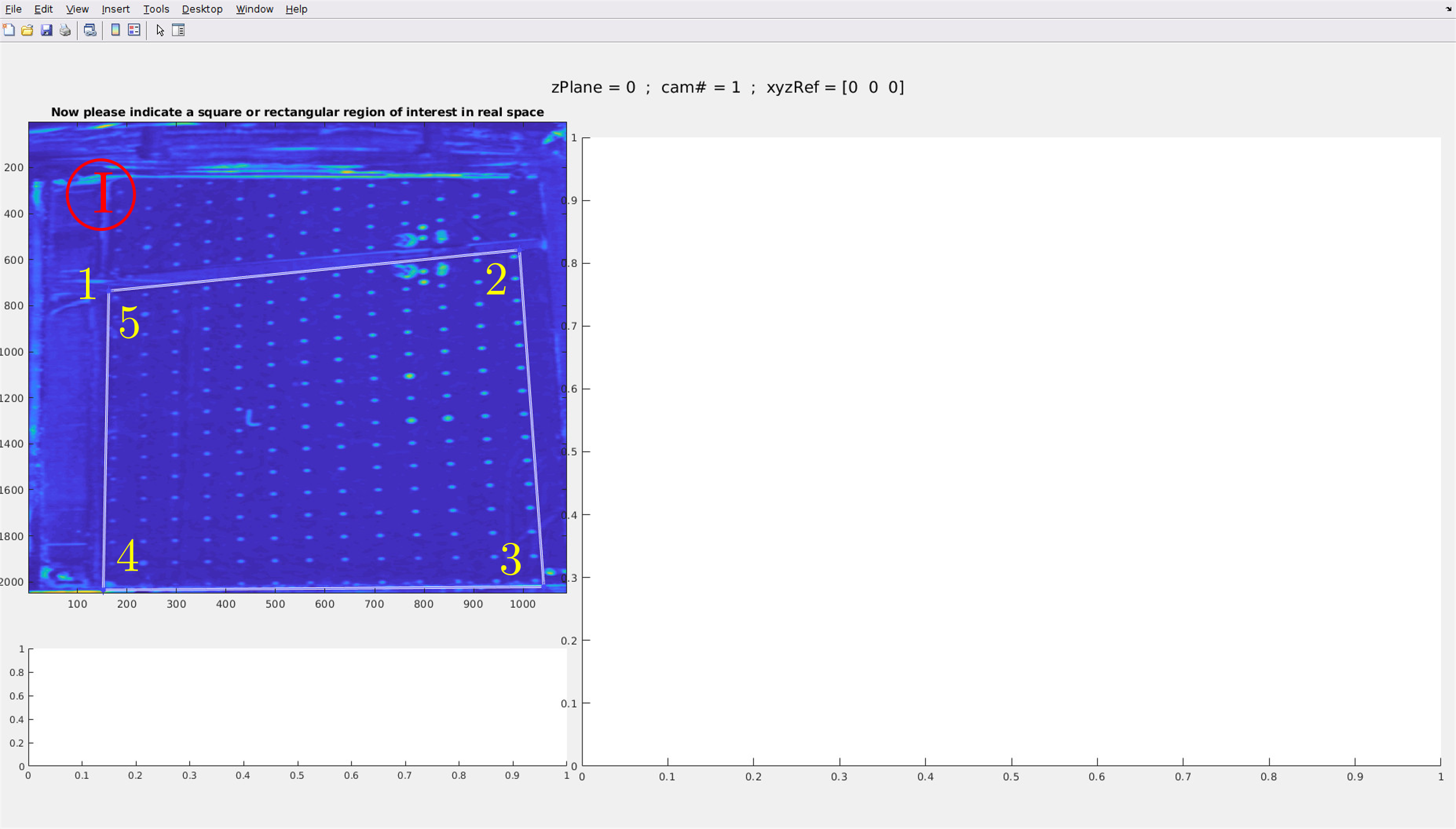
MakeCalibration.mfunction? A figure appears when the function is called. The raw calbration picture is shown on the upper left panel. The mire limits has to be given to the function. To do that, click on the corners of this rectangle starting by the upper left corner and then continue clockwise. The point detection is easier when mire points are in a rectangle on the picture.
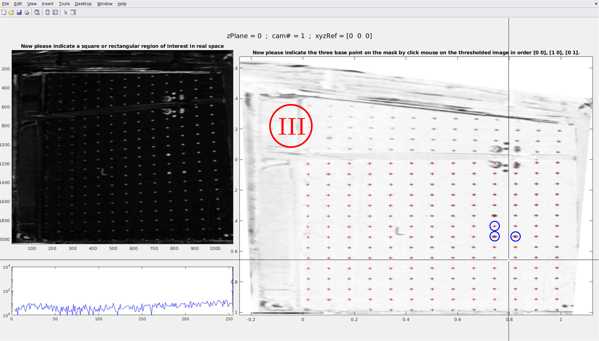
Then rightclic (a menu is opened) and click on Create a mask. On the right the corrected picture is then printed.
Redcrosses on the corrected picture note detected points. If many points are not detected, that means that the threshold argument was not good and nedd to be decreased. Some points are always misplaced and need to be suppress. By clicking on them, a circle will appear arround them mainning there will be suppress in the following steps. If some points are missing, press on a and then click, a green cross appears, it is a new point. When all points are detected rightclic.
You need to click on the origin and on two points to define axis. Please click on the origin, then on the x-axis and finally on the y-axis. The order is important. On the following picture, blue circles surround these 3 points.
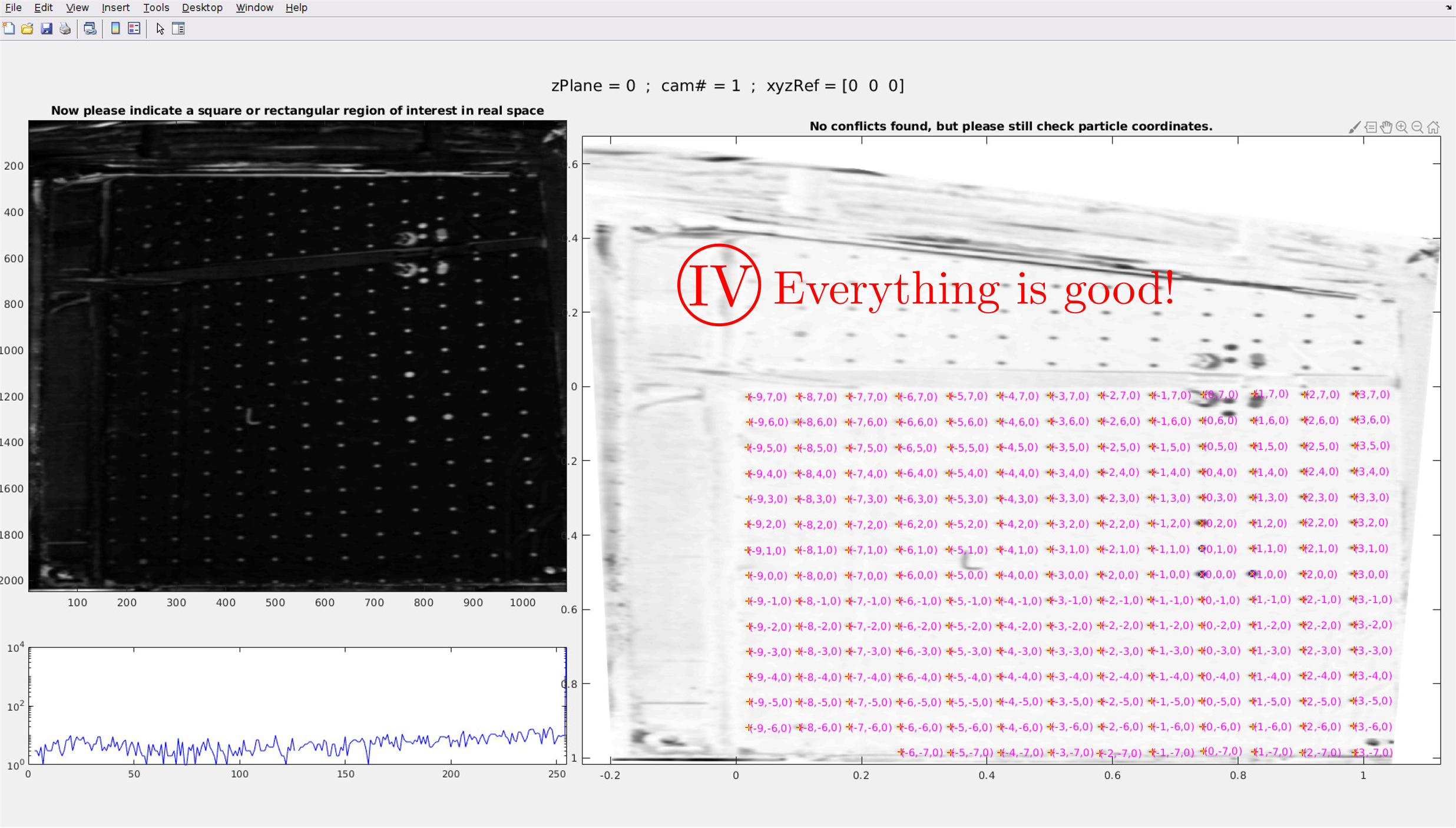
All coordinates of calibration points are shown. Please control that no error occurs at this step. If some points are missing or are misplaced, you need to start again from 1. Go to
MATLABinstance and doCtrl+Cto stop the function.
Warning
- Missing points:
When a point of the mire is not detected, the measurement volume is reduced because when a particle goes in this area, we will not be able to detect it precisely. That is why it is important to detect as much particles as possible on the calibration pictures.
- Run the
MakeCalibration.mfunction from a specific plane: After a mistake during point detection, it is necessary to stop the function doing
Ctrl+Cbut it is appreciable to start again the detection at the same calibration picture. The arguments FirstPlane and FirstCam are made for that. The function will start at FirstPlane and loop over camera number between FirstCam and the last camera.
- What are calibration data?
- The file
calib.matis composed of several data as described below: posPlane : z position which corresponds to kz plane
pimg : detected mire points on the calibration picture (2D) in px units,
pos3D : detected mire points in 3D space and in SI units,
movedpoints : index of moved points,
addedpoints : index of added points,
T3rw2px : Cubic transformation from real world to px. Pay attention T3rw2px~=inverse(T3px2rw) !,
T1px2rw : Linear transformation from px to real world. T1rw2px=inverse(T1px2rw),
T3px2rw : Cubic transformation from px to real world,
cHull : coordinates of the region of interest,
name : camera number (kcam),
dirPlane : [i,j,k] axes orientation. i,j = axis provided by the calibration mire, k is the axis along which the mire is displaced. For instance, if the mire is in the plane (Oxy) and that it is displaced along z axis, dirPlane=[1,2,3].
The main data are linear and cubic transformation which allows you to go from pixels to real world and inversely doing
% To transform image to real world use:
[x_rw,y_rw,z_rw] = transformPointsInverse(Trw2px,posimg(:,1),posimg(:,2));

% To transform real world positions to image positions use:
[x_px,y_px] = transformPointsInverse(Tpx2rw,pos3D(:,1),pos3D(:,2),pos3D(:,3));
This is often confusing so it needs a bit of reflexion.
Two types of transformations are performed. The linear transformation T1 which is the simplest one. As T1rw2px is the inverse of T1px2rw (
T1rw2px=inverse(T1px2rw)), it is sufficient to save only one of them. The cubic transformation T3 is a third order polynomial transformation which takes into account optical deformations but which could also create diverging points. As it is a 3rd order polynomial transformation T3rw2px is no more the inverse of T3px2rw (T3rw2px~=inverse(T3px2rw)) so both are saved in the calibration file. Other transformations can be computed, even a posteriori, using the pimg and pos3D data of the calib structure.- The file
- How to check if your calibration is ok?
You can do is to use the function
Calib_visualisation.m, in the Test directory, wich will overlay the point that you placed during the calibration and the raw images. If everything is fine, you should see crosses only on the black dot of the calibration plate.